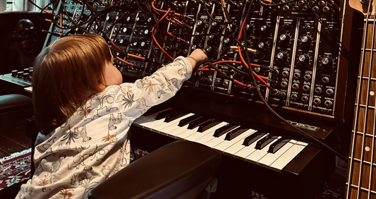
Gates and Triggers Explained

The goal of this page is to squash the confusion over Gates and Triggers.

In the Beginning,

Dr. Bob Moog's modular systems used a signal called "Trigger" to identify when a key on the keyboard was pressed and released. This signal could also be generated by other sources such as foot pedals and drum controllers. Triggers are used to start envelope generators, sequencers, etc, and are a critical function in any synthesizer system. Moog systems use 2 types of Triggers: Voltage Triggers (AKA V-Trig) and Switch Triggers (AKA S-Trig, sometimes called Shorting Trigger).

Voltage Triggers

voltage trigger

V-Trig signals are patched using normal 1/4" plugs and jacks, and in a Moog modular are approximately 3 volts when ON and 0 volts (Ground) when off. V-Trigs in a Moog modular are created by the 960 Sequential Controller (90% duty cycle) and by the 961 interface that can convert S-Trigs to V-Trigs. V-Trigs are the same as what we call 'gate' today and that's what Synthesizers.com modules use. Gate signals allows for easier, more intuitive patching and eliminates the need for conversion. With V-Trig and modern gates, you can patch gates right along with audio signals using the same patch cords and do things like fire envelope generators with oscillators.
 

Switch Triggers

Switch Trigger

S-Trig signals are different than V-Trigs and use a special 2-pin blade-type connector made by Cinch/Jones. Basically, an S-Trig is just a passive switch closure to ground. This means an S-Trig is an inverted version of V-trig, and without the high-side voltage. Moog keyboards produce S-Trigs and Moog 911 Envelope Generators use them to control their cycle. One advantage of S-Trigs is that many source signals can be connected in parallel to create a logical OR arrangement so any signal makes it through. I believe this was Bob's intended goal and he thought it would be important for adding a multitude of controllers. The disadvantage of S-Trig is that it is not readily patched like other signals because it uses a special connector and signal, and it must go through a conversion module to interface to modules requiring a V-Trig.

Today,

Today, virtually all synthesizers use 'gates' which are essentially V-Trigs. Typically modern gate voltages are +5 volts or more. Usually they have a positive polarity, but not always, and some synthesizers have a switch to select polarity.

Yet Another Type of Trigger

To confuse matters worse, some systems have a signal called 'Trigger' that is neither a gate (V-Trig) or a S-Trig, but instead is a short positive-going pulse that happens only at the initiation of a keypress. Some envelope generators can accept this type of trigger to RE-Trigger it before the envelope cycle completes.

Converting to Switch Triggers

Switch Trigger Cable

You won't need to convert between S-Trig and V-Trig (gates) unless you're using older Moog-style systems, because most modern equipment uses gates exclusively.

If you need to convert a gate (V-Trig) to S-Trig, use this special cable. You can use this cable to convert gate signals from a Synthesizers.com system to Switch Trigger signals needed to activate Moog envelope generators. It has a male 1/4" plug on one end (the gate end) and a 2-pin Cinch/Jones plug on the other. Here's the circuit if you want to make your own.

To convert from a Moog Switch Trigger to a voltage gate needed by Synthesizers.com modules, you'll need to run the Moog Switch Trigger signal through the Moog 961 module to create a voltage. You can also use the Q142 Pedal Interface which will convert any mechanical switch to a voltage level.

Summary - Gates and Triggers in a nutshell

Here are the main things to know.

  • Gates are on/off signals, usually from a keyboard controller to indicate a keypress.
  • Voltage-Triggers are also called V-Trigs and are the same as gates, and are normally a positive voltage around 3-5 volts.
  • Almost all modern synthesizers use positive gates.
  • Switch-Triggers are also called S-Trigs, and are switch-to-ground signals - not used much any more.

Read more →

Q119 and Q960 Sequencer Comparison

Function

Both the Q119 and Q960 sequencers create control voltages for use by other modules. The difference is various features that allow the sequence to be controlled.

Internal Oscillator

Both sequencers have an internal oscillator but the Q960's oscillator has voltage controlled frequency and will track a keyboard fairly well. This can be used to create a fancy oscillator with manual control over the waveform. The oscillator also has a finer manual control over the frequency via a multi-position range switch.
The Q119's oscillator is not voltage controlled but the same functionality can be had by using a Q106 oscillator to drive it.
Both sequencers can be driven by an external pulse source such as an oscillator or keyboard gate.

Rows and columns

The Q119 sequencer can operate as 3x8 (3 rows of 8 stages) or 1x24 (1 row of 24 stages). This allows long sequences without having to patch additional modules.
The Moog-style Q960 has 3 rows of 8 stages but can be patched into a Q962 switch module to produce 1 row of 24 stages. A little work but not a problem. 

Control

The Q960 has a button and jack to turn the internal oscillator ON and OFF. The Q119 goes further and offers a GO input which causes the oscillator to stay on as long as the input is on.
 

Sequences

The Q119 offers a switch for Up or Up/Down sequences, and a switch for Once or Continuous mode. The Q960 sequencer can not perform Up/Down since it's a shift register design, but can produce Once or Continuous by setting the 9th stage to Off or Skip.
 

Stage Advancement

Both sequencers allow manual or external stage advancement.
 

Gate Output

The Q119 has a gate output for each row, and a master gate output for when the unit is in 1x24 mode. The gate width is adjusted with a pot, or can be voltage controlled by controlling the pulse width of an external oscillator.
The Q960 has a gate (Trigger) output for each stage but each output is on for the duration of the stage's on-time (100%). This prevents adjacent outputs from creating distinct gate pulses when combined. The gate outputs can be patched back into other gate inputs to create interesting patterns. The Q960 also provides a pulse output from the internal oscillator but it is fixed at 90%.
 

Mode Switches

The Q960 has a mode switch for each stage with options: Skip, Normal, Stop. This is very fun to play with in real-time while the sequence is playing. The Q119 does not have a mode switch for each stage.
 

Stage On-Time

The Q119 can offer stage on-time control, but only by using an external oscillator controlled by the 3rd row.
The Q960 has built-in stage on-time control which uses the 3rd row knobs.
 

End Stage

The Q119 has an button to set the last stage.
The Q960 sets the end stage by either patching a trigger output back to the stage #1 input, or by setting stage mode switches to Skip. A reset feature is offered for the Q960 that provides another position on the mode switch to force stage #1.
 

Output Section

The Q119 offers gate and voltage outputs for each of the 3 rows, plus master outputs. The master output offers a glide control, a voltage add input, and a manual voltage add control. A voltage range switch toggles between 0-5v or -5-5v output ranges.
The Q960 has dual voltage outputs for each row, along with a 3-position voltage range switch for each. Position 1=0-2v, 2=0-4V, 4=0-8V.
 

Size and Power

Both the Q119 and Q960 sequencers consume 8 module spaces and will fit in a 5U tall rack frame. Both modules require +15, -15, +5 volts but the Q960 requires more current on the +15 volt rail to run the incandescent lamps. This is usually never a problem.
 

Price

The Q119 is substantially cheaper than the Q960, plus the Q960 typically requires a Q962 switch to increase functionality which further widens the gap.
 

Maintenance

The Q119 uses LEDs which essentially last forever.
The Q960 uses 16-volt incandescent lamps which are true to the vintage Moog look but dim quickly at high switching speeds, and tend to burn out regularly. There is a great variability with these lamps, some will last a long time, some not so long. They are easy to replace from the front panel and not very expensive. See the parts page for replacements.

Conclusion

The Q119 and Q960 are both excellent sequencers but with different features. The Q960 offers more control via gate inputs and outputs, and the mode switch makes changing patterns in real-time very fun. The Q960 requires a Q962 switch to produce 24-stage sequences and can't produce up/down sequences like the Q119, but the Q119 would require an external Q106 oscillator to produce stage timing and track a keyboard.


A difficult decision I know. Ultimately the user will have to decide based on the features offered and the budget. Maybe toss a coin and see if you like the results?

  • Chip Wrote: I just received the Q119 Sequencer. What a great combination of efficient design and good craftsmanship.
  • JS Wrote: That Q960 is really quite an amazing sequencer, especially along with the Q962.

Read more →

First Learn Blog Post

This is the first learn blog test post.

Read more →

Sync Sequencers to Other Gear

Here are some ideas about syncing sequencers to other gear including your computer workstation.

MIDI Note Gates

Send MIDI notes to the 2nd channel of the Q174 MIDI Interface module and use that gate to start or clock sequencers.


MIDI Gates Module

The Q170 MIDI Gates module decodes MIDI sync messages including Clock, Start, Stop and Continue. The Clock message can also be divided up to /192.


Audio Click Track

Send audio to the Q118 Instrument Interface module which will create a gate that can be used to start or clock sequencers. Use the SHIFT input on the Q960. You might need to boost or attenuate with the Q125 Signal Processor module.


Sequencer Links

Q119 Sequencer
Q960 Sequencer
Compare Sequencers

Ideas from Scott L.

When shifting the Q960 from an external clock signal (derived from a MIDI source like a DAW), it is helpful to have the Q960 comes to rest on Stage-9 whenever the DAW or MIDI source is stopped. This can be easily achieved in a number of ways. The Q170 allows any of the gate outputs to be set to send a pulse when a START or STOP command is received at the MIDI input (all MIDI devices sending MIDI clock send both a START and STOP command whenever the transport is started or stopped). Route that Q170 gate output to the Q960 Stage-9 gate in and the Q960 will always instantly locate to Stage-9 whenever the master clock is stopped. There is no need to feed any gate signal into Stage-1. When the master clock is restarted, the first clock pulse received at the Q960 SHIFT input will cause the Q960 to correctly start on Stage-1.

This same functionality can be achieved using a Q174, by entering a simple MIDI command anywhere on the timeline that you might wish to have a Q960 go to Stage-9, or to have a Q119 reset at the beginning of a sequence. Using the Q174 in mode 3, the third CC output jacks sends a trigger when receiving MIDI CC4, so inputting a simple CC4 on a timeline (one entry with CC4 at value 127 followed right after by another at value 0), will cause a trigger pulse to come out of jack 3 on the Q174. This can be used for many things including resetting a Q119 or Q960.

Ideas from Paca

There seems to be an idiosyncrasy that occurs when a Q960 or Q119 sequencer is slaved to a MIDI clock; upon receiving the first clock signal on Start from the MIDI Clock source (like a DAW), the sequencer jumps to Stage #2, skipping Stage #1 altogether. The same thing occurs regardless of at what Stage you wish to start your sequence; it will jump to the next step. I have yet to find a concrete solution, even after trying 3 different MIDI Clock to CV converters including the Q170 MIDI Gates module, which is my current choice. But there are a few workarounds.

On the Q960, send a trigger (gate) signal on Stop to either the last Gate Input of your sequence, or better still (thanks Scott L. for this idea!), send that Stop/Reset gate signal to Stage #9, regardless of the length of your sequence. As Scott points out, this is a 0 voltage Stage and will prevent hanging notes on stop in may cases. Regarding the Q119, Scott suggests using a Trigger Delay, should you have one. I have tried this idea and have had inconsistent results. While this may very well be pilot error on my part, I have have chosen instead to start the programming of my Q119 sequence on Stage #2. That means, say, if you are creating a 24 step sequence, Stage #1 would be your 24 step. As brain-twisting as this can be at times, it always works.

Ideas from Richard S.

Here's an alternative method which is REALLY analog, and involves NO MIDI: Actually record one (or more) tracks (can be temporary)... like a snare track... cymbal... or even just a click track.... just anything with a short duration. Then use that (those) track(s) audio to drive the 'shift' input of the Q960. I found that often, I didn't need to patch thru a Q125 Signal Processor if unavailable... just anything handy that will attenuate. So... the short version... use audio to drive the sequencer(s) & switch(es).

Read more →